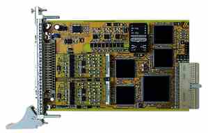
CPCI-1710 Isolated Fuction-Programmable Counter Board |
Çϵå¿þ¾î Ư¡
Depth & 5MHz Counting Frequency
24V Signals(CPCI-1710-24V)
Functions
Incremental Encoders (90° Phase-Shifted Signals)
The SSI function is an Interfece for systems which allow an Absolute Position Informa- tion via Serial Data Transfer
Available Lines for Each Function Module 8 Lines are Available for Each Function Module
- 2 x TTL and RS422(CPCI-1710) or 2 x 24V(CPCI-1710-24V) - 3 x 24V, Optional 5V for Channels E, F, G
- 1 x 24V, Optional 5V(Power Output)
or Output, Isolated : 2 x TTL, RS422 |
Available Functions, When all four Function Modules are Programmed
Measurement
Measurement
Safery Features
- Windows 2000/NT/98/95 - Windows 3.11, MD-DOS
- Windows 2000/NT/98/95
- Microsoft VC++ 5.0/Microsoft C 6.0 - Borland C++ 5.01/Borland C 3.1 - Visual Basic 4.0/5.0 - Delphi 1.0/4.0 - Turbo Pascal 7.0
- Diadem 6
(Depending on the Function)
CE Certification
ÀÀ¿ë ºÐ¾ß
|
¸ð µ¨ ¹ø È£ |
ºñ °í |
CPCI-1710 |
Multifunction Counter Board, Isoaled, 3U European Size |
Options |
|
URS-1710 |
CPCI-1710 with 6U Bracket |
24V
|
24V for differential Input Signals ( Channel A to G)(A and B for Counter, I<Index> and UAS(error) Signal) |
5V |
24V Signals with 5V( Channels E, F, G ) |
Accessories |
|
ST370-16 |
Shielded Round Cable, 2m |
Screw Terminal Board for DIN-rail |
CPCI-1710 Çϵå¿þ¾î »ç¾ç |
|
Parameter |
Descriptions |
Counting Component |
|
Counting Depth |
32-bit |
Counting Frequency |
Up to 5MHz |
Function Freely Re-Programmable |
|
Acquisition of Incremental Encoders |
|
Acquisition of Absolute Encoders/SSI |
|
Counter/Timer |
|
Chronos/TOR for Frequency Measurement |
|
Pulse Acquisition |
|
Chronos for Pulse Width Measurement |
|
Chronos for Period Duration Measurement |
|
TOR for Velocity Measurement |
TOR Function |
Digital I/O, 24V, TTL, RS422 |
|
PWM(Pulse Width Modulation) |
PWM Function |
ETM(Edge Time Modulation) |
ETM Function |
Tailored Functions |
|
Signals |
|
|
Digital I/O Signals, TTL or RS422 |
Input Channels |
|
Number of Channels |
20 |
Differnecial Input Channels |
|
Differencial Inputs, 5V |
8 |
Nominal Volatge |
5VDC |
Common Mode Range |
+12 / -7V |
Max. Differencial Voltage |
±12V |
Input Sensitivity |
200mV |
Input Hysteresis |
50mV |
Input Impedance |
12 k§Ù |
Terminal Resistor |
150 §Ù Serial with 10nF(typ.) |
Signal Delay |
120 ns (at Nominal Voltage) |
Max. Input Frequency |
5 MHz (at Nominal Voltage) |
Mass-Related Inputs, 24V (Channel E, F, G) |
|
Numer of Inputs |
12 |
Nominal Volatge |
24VDC |
Input Current at Nominal Volatge |
11 mA |
Logic Input level
|
Unominal : 24V |
UH Max. : 30V |
|
UH Min. : 17V |
|
UL Max. : 15V |
|
UL Min. : 0V |
|
Signal Delay |
120 ns (at Nominal Voltage) |
Max. Input Frequency |
2.5 MHz (at Nominal Voltage) |
Output Channels |
|
Nominal Voltage |
5VDC |
Maximal Output Frequency |
5MHz (Diff. Output Channels) |
Max. Number of Output |
8 (if they are not use as Diff. Inputs) |
Digital Output, 24V |
|
Output Type |
High-Side (Load at Ground) |
Number of Outputs |
4 |
Nominal Voltage |
24VDC |
Range of Voltage Output Supply |
10V to 36VDC (through 24V Ext. pin) |
Max. Current for 4 Output Channels |
2A typ. (Limited to the Voltage Supply) |
Max. Output Current |
500mA |
Short-Circuit Current/Output Shut-Down at 24V, RLoad<0.1§Ù |
1.5A Max. (Output Switches Off) |
RDS ON Resistance |
0.4 §Ù Max. |
Overtemperature |
170 ¡É (All Outputs Switch Off) |
Protection against Overtemperature(24V Outputs) |
|
Activated Deactivated(Automatically) |
from approx. 150-170¡É(Chip temperature) from approx. 125-140¡É(Chip temperature) |
Outputs (at Overtemperature) |
All Outputs Switch Off |
Under Voltage (Effective at Vext < 5V) |
|
Output (at Undervoltage) |
All Output Switch Off |
Switching Characteristics of the Outputs (Vext = 24V, T = 25¡É, Ohmic Load : 500mA) |
|
Switch ON Time |
200 §Á |
Switch OFF Time |
15 §Á |
Digital Output Channels, 5V (Option) |
|
Output Type |
TTL |
Number of Outputs |
4 |
Nominal Voltage |
5VDC |
Switching Characteristics of the Outputs (T = 25¡É, TTL Load) |
|
Switch ON Time |
0.06 §Á |
Switch OFF Time |
0.02 §Á |
Safety |
|
Optical Isolation |
1000V |
Noise Immunity |
|
Test Level
|
- ESD: 4kV - Field: 10V/m - Burst: 4kV - Conducted radio interferences: 10V |
Physical & Environmental Conditions |
|
Dimensions |
3U/4TE |
System Bus |
CompactPCI 32-bit 5V acc. to 2.1(PCISIG) |
Space Required |
1 slot |
Operating Voltage
|
+5V, ±5% from the PC +24V ext. / 10mA |
Current Consumption |
CPCI-1710 : 600mA typ. ±10% |
Front Connector |
50-pin SUB-D male connector |
Temperature Range |
0 to 60 ¡É(with forced cooling) |
CPCI-1710 Configuration Example
Function : Incremental Counter Function |
Descriptions |
With this function, the module is programmed as a fast Counter (A, B) for;
This module Programmed with this function is connected with up to 2 incremental Encoders which can be resp. configured as follows;
(Option 24V : APCI-1710-24V)
|
Function Range of the Function Module |
synchronised with an Internal Clock Pulse
through the Data Bus
or by Writing in Register
|
Incremental Counter Function : Connection Example
|
Incremental Counter Function : Used Signals
Signals |
On SUB-D |
Polarity |
Function |
CHA1CLK +/-
|
Ax +/-
|
Diff. / TTL / 24 V*
|
A-signal of the 1st incremental encoder |
CHB1DAT +/-
|
Bx +/-
|
Diff. / TTL / 24 V*
|
B-signal of the 1st incremental encoder |
CHIx +/- INDEX
Cx
|
Cx +/-
Cx +/-
|
Diff. / TTL / 24 V*
Diff. / TTL / 24 V*
|
INDEX signal of the incremental encoder in 32-bit mode A-signal of the 2nd incremental encoder in 16-bit mode |
CHUx +/- UAS Dx
|
Dx +/- Dx +/-
|
Diff. / TTL / 24 V* Diff. / TTL / 24 V*
|
Error signal input in 32-bit mode B-signal of the 2nd incremental encoder in 16-bit mode |
Z1-EXREF REF
|
E
|
24V/5V Optional
|
Nomal Digital input, readable through register, can control the reference point logic |
Z1-EXSB-A ExtStrb_a
|
F
|
24V/5V Optional Active High
|
Digital input which latches the counter 16/32-bit in the 1st latch register. Can generate an interrupt |
Z1-EXSB-B ExtStrb_b
|
G
|
24V/5V Optional Active High
|
Digital input which latches the counter 16/32-bit in the 2nd latch register. Can generate an interrupt |
x : Number of the Function Module(See pin assignment)
* : 24V with board version APCI-1710-24V
CPCI-1710 Incremental Counter Function Pin Assignment
|
Function : Synchronous Serial Interface |
Descriptions |
The module is programmed as a Synchronous Serial Interface (SSI). The SSI function is an interface for systems which allows an absolute position information through serial data transfer. |
Applications |
|
Connection of 1 to 3 SSI Encoders for Each Function Modules |
|
The Interface includes |
|
SSI Function : Used Signals
Signals |
On SUB-D |
Polarity |
Function |
CLOCK_x |
Ax +/- |
Diff. |
CLOCK Output signal for the SSI encode |
DATA1_x |
Bx +/- |
Diff. / TTL / 24V* |
DATA input for the 1st encoder |
DATA2_x |
Cx +/- |
Diff. / TTL / 24V* |
DATA input for the 2nd encoder |
DATA3_x |
Dx +/- |
Diff. / TTL / 24V* |
DATA input for the 3rd encode |
Input1_x |
Ex |
24V / 5V Optional |
Digital Input |
Input2_x |
Fx |
24V / 5V Optional |
Digital Input |
Input3_x |
Gx |
24V / 5V Optional |
Digital Input |
Output_x |
Hx |
24V / 5V Optional |
Digital Output |
x : Number of the Function Module(See pin Assignment)
* : 24V with board version APCI-1710-24V
SSI Function : Block Diagram
|
SSI Function : Connection Example
|
CPCI-1710 SSI Function Pin Assignment
|
Function : Counter/Timer Function (Equivalent to 82C54) |
|
Descriptions |
|
The module programmed with this function can be used as a programmable interval timer/counter (similar to 82C54) with 3 x 32-bit. This multitiming component can be considered as a group of I/O ports in the system software. It generates time delays through software control. Instead of setting up timing loops in software, the user programs the module for the desired delays. After this delay, the module will interrupt the PC.
Channels for avoiding earth circuit
and Interrupt Status Resister
|
|
Programmable Mode |
|
3 x 32-bit Counter/Timers are available on one Function Modules. Each Counter/Timer can be Programmed Independently in one of the following Modes. Mode Definition CLK PULSE : Falling Edge after a rising edge of the counter clock input. TRIGGER : Rising Edge of the counter gate input. COUNTER LOADING : Counter transfer from the counter resister to the counter
|
|
Typical Applications |
|
|
|
Counter/Timer Function : Used Signals
Signals |
On SUB-D |
Polarity |
Function |
OUT 0 |
Ax +/- |
Diff. / TTL |
Output Channel of the 1st Counter/Timer |
OUT 1 |
Bx +/- |
Diff. / TTL |
Output Channel of the 2nd Counter/Timer |
OUT 2 |
Hx |
24V / 5V Optional |
Output Channel of the 3rd Counter/Timer |
Gate 0 |
Ex |
24V / 5V Optional |
Gate Input of the 1st Counter/Timer |
Gate 1 |
Fx |
24V / 5V Optional |
Gate Input of the 2nd Counter/Timer |
Gate 2 |
Gx |
24V / 5V Optional |
Gate Input of the 3rd Counter/Timer |
CLK 0 |
|
|
Internal Clock (PCI clock/4) |
CLK 1 |
Cx +/- |
Diff. / 24V* |
Clock Counter Input of the 2nd Counter/Timer |
CLK 2 |
Dx +/- |
Diff. / 24V* |
Clock Counter Input of the 3rd Counter/Timer |
CPCI-1710 Counter/Timer Function Pin Assignment
|
Function : Chronos |
Descriptions |
The "Chronos" function is a Timer Interface which allows to measure the between two "Events" like a Chronometer. 3 Functions are available :
Signal and the Stop Pulse Signal
|
Properties |
for avoiding earth circuit
|
Chronos Function : Used Signals
Signals, On SUB-D |
Polarity |
Function |
Ax +/- |
Diff. / TTL |
Digital Output 1; Set to "0" after Reset |
Bx +/- |
Diff. / TTL |
Digital Output 2; Set to "0" after Reset |
Cx +/- |
Diff. / TTL / 24 V * |
Start Pulse for Measuring |
Dx +/- |
Diff. / TTL / 24 V * |
Stop Pulse for Measuring |
Ex |
24V / 5V Optional |
Digital Input 0 |
Fx |
24V / 5V Optional |
Digital Input 1, Inverting |
Gx |
24V / 5V Optional |
Digital Input 0, Inverting |
Hx |
24V / 5V Optional |
Digital Output 0; Set to "0" after Reset |
x : Number of the Function Module(See in pin Assignment)
* : 24V with board version : APCI-1710-24V
Chronos Function : Used Signals
|
CPCI-1710 Chronos Function Pin Assignment
|
Function : Pulse Counter |
Descriptions |
The "Pulse Counter" is an interface for the acquisition of External Digital Pulses. Each rsising or falling edge on the counter input starts decrement on the initially set counter value. An Interrupt is generated at logic "0", i.e. the Digtal Output is set or reset.
|
The Interface Includes |
|
Pulse Counter Function : Used Signals
Signals |
On SUB-D |
Polarity |
Function |
CHAxCLK +/- |
Ax +/- |
Diff. / TTL / 24V* |
Input of the 1st Counter |
CHBxDAT +/- |
Bx +/- |
Diff. / TTL / 24V* |
Input of the 2nd Counter |
CHIx +/- |
Cx +/- |
Diff. / TTL / 24V* |
Input of the 3rd Counter |
CHUx +/- |
Dx +/- |
Diff. / TTL / 24V* |
Input of the 4th Counter |
Zx-Out |
H |
24V / 5V Optional |
Common Digital Input of the Counter |
x : Number of the Function Module(See in pin Assignment)
* : 24V with board version : APCI-1710-24V
Pulse Counter Function : Connection Example
|
Function : Digital I/O |
Descriptions |
The Digital I/O function allows an easy access to the Digital I/O available on the function modules. The I/O level of the Input and Output channels are read and set or reset through read/write commands. The Digital I/O have no logical connection to each other. The connec- tion can only be made through software. The complete Isolation through Optical Couplers avoids earth circuits. When the "Digital I/O" function is programmed on all function modules, up to 28 Digital Input and 12 Digital Output channels are available. |
Available Channels |
Software configuration. |
Digital I/O Function : Used Signals
Signals |
On SUB-D |
Polarity |
Function |
C |
Cx +/- |
Diff. / TTL / 24V* |
Digital Input |
D |
Dx +/- |
Diff. / TTL / 24V* |
Digital Input |
E |
Ex |
Diff. / TTL / 24V* |
Digital Input |
F |
Fx |
24V / 5V Optional |
Digital Input |
G |
Gx |
24V / 5V Optional |
Digital Input |
H |
Hx |
24V / 500mA (10..36V) |
Digital Output |
A |
Ax +/- |
Diff. / TTL / 24V* |
Digital Input or Output |
B |
Bx +/- |
Diff. / TTL / 24V* |
Digital Input or Output |
x : Number of the Function Module(See in pin Assignment)
* : 24V with board version : APCI-1710-24V
Digital I/O Function : Block Diagram
|
CPCI-1710 Digital I/O Function Pin Assignment
|
CPCI-1710 Å͹̳Πº¸µå ¿¬°áµµ
|
Çѱ¹ÀÎÅÚ¸®Á¯Æ®½Ã½ºÅÛ(Korea Intelligent System) ÀüÈ : 02-3272-9301 Email : sales@intelligent.co.kr |