하드웨어 특징
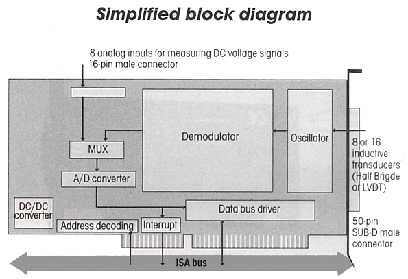
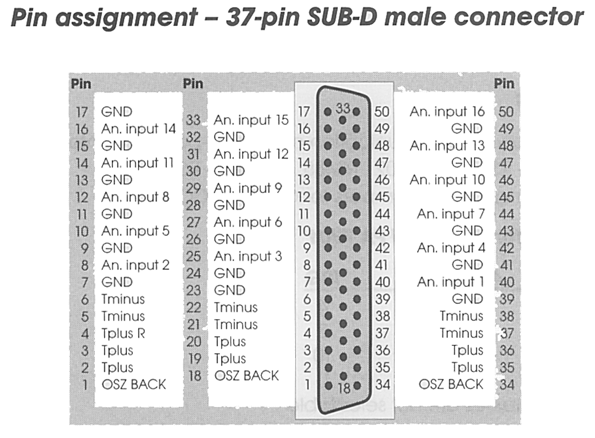
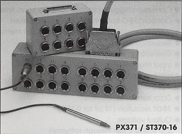
![]() Acquisition of 16
or 8 Inductive
Acquisition of 16
or 8 Inductive
Displacement Transducers
(Half Bridge, LVDT)
![]() 16 or 8 Input Channels
16 or 8 Input Channels
![]() 14-bit Resolution
14-bit Resolution
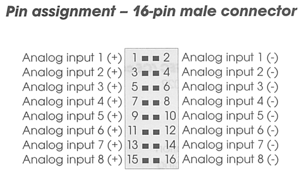
![]() 8 Input Channels can be configured for
8 Input Channels can be configured for
Measuring DC Voltage Signals(±10V)
![]() Data Transfer Rate
: 50kHz
Data Transfer Rate
: 50kHz
![]() Conversion can be Triggered through
Conversion can be Triggered through
Software
![]() End of conversion
inquired through
End of conversion
inquired through
Software
![]() Interrupt possibility
at end of conversion
Interrupt possibility
at end of conversion
![]() The base address occupies 2 I/O
The base address occupies 2 I/O
addresses in the 64KB I/O address space
![]() Addressing through DIP switches
Addressing through DIP switches
![]() Switching time of the reset relay : 2s
Switching time of the reset relay : 2s
Safely
![]() Noise
Neutralization on the PC supply
Noise
Neutralization on the PC supply
![]() Software
Drivers
Software
Drivers
- Windows 2000/NT.98/95, MS-DOS
![]() Real
Time Drivers for :
Real
Time Drivers for :
- Windows 2000/NT/98/95
![]() LabVIEW 5.01
LabVIEW 5.01
![]() LabWindows/CVI
5.01
LabWindows/CVI
5.01
![]() Samples
programs :
Samples
programs :
- Microsoft VC++ 5.0/Microsoft C 6.0
- Borland C++ 5.01/Borland C 3.1
- Visual Basic 1.0/5.0
- Delphi 4
- Turbo Pascal 7.0
CE Certification
![]() EN 50082-2, EN 55011, EN
55022
EN 50082-2, EN 55011, EN
55022
응용 분야
![]() Automated
Gauging
Automated
Gauging
![]() Quality
Control
Quality
Control
![]() Industrial
Process Control
Industrial
Process Control
![]() Automatic
Test Equipment
Automatic
Test Equipment
![]() R&D
Instrumentation
R&D
Instrumentation