PA302 Analog Input Board


Analog Input Channels

square02_darkbluegreen.gif 16 Single-Ended/8 Differential Channels

  or 8 Single-Ended/4 Differential Channels

square02_darkbluegreen.gif 12-bit Resolution

square02_darkbluegreen.gif Data Transfer Rate : 125kHz

square02_darkbluegreen.gif Input Range :

  ±10V, 0-10V, ±5V Jumper-Selectable,

  0(4)-20mA Optional(Option DC or SC)

square02_darkbluegreen.gif Gain INA(Instrumentation Amplifier),

  Adjustable through Jumper or Resistance

square02_darkbluegreen.gif Conversion Start through Software,

  External Trigger or Programmable Timer

square02_darkbluegreen.gif Addressing through DIP Switches

square02_darkbluegreen.gif Interrupt: IRQ 3, 5, 10, 11, 12, 14, 15

square02_darkbluegreen.gif 3 x 16-bit Timers(82C54)

  Timer 0 : Only for the Analog Acquisition

  Timer 1 & Timer 2 as Cyclic Time-Counter


Digital

square02_darkbluegreen.gif 2 Digital Open COllector Output Channels


Safery Features

square02_darkbluegreen.gif Protection against Overvoltage &

  High-Frequency EMI

square02_darkbluegreen.gif Noise Neutralization of the PC Supply

Analog Acquisition

square02_darkbluegreen.gif Automatic Analog Acquisition through

  Cyclic-Timer Control

square02_darkbluegreen.gif Acquisition Triggered through Software,

  Timer, External Event

square02_darkbluegreen.gif Trigger Functions

  - Software Trigger or

  - External Trigger : The Analog Acquisition

     (Single or Scan) is started through an

     External TTL signal switching from 0 to

     5V on the TTL Input Channel

square02_darkbluegreen.gif Interrupt : End of Single Channel, End of

  MultiChannel, End of Scan List


Áö¿ø ¼ÒÇÁÆ®¿þ¾î

square02_darkbluegreen.gif Standard Drivers :

  - Windows 2000/NT/98/95

  - WIndows 3.11, MS-DOS

square02_darkbluegreen.gif LabVIEW 5.01

square02_darkbluegreen.gif Samples programs :

  - Microsoft VC++ 5.0/Microsoft C 6.0

  - Borland C++ 5.01/Borland C 3.1

  - Visual Basic 1.0/4.0/5.0

  - Turbo Pascal 7.0

square02_darkbluegreen.gif On request :

  - LabWindows/CVI 5.01


CE Certification

square02_darkbluegreen.gif EN 50082-2, EN 55011, EN 55022


ÀÀ¿ë ºÐ¾ß

square02_darkbluegreen.gif Industrial Process Control

square02_darkbluegreen.gif Industrial Measurement

square02_darkbluegreen.gif Signal Analysis

square02_darkbluegreen.gif Acquisition of Sensor Data


¸ð µ¨ ¹ø È£

ºñ       °í

PA302-8

8 Single-ended or 4 Differential Inputs, 2 DO Open Collector

PA302-16

16 Single-ended or 8 Differential Inputs, 2 DO Open Collector

Options

SF

Filter for 1 Single-ended Channels, 33Hz

DF

Precision Filter for 1 Differential Channels, 30Hz

DC

Current Inputs for 1 Differential Channels, 0(4)-20mA

SC

Current Inputs for 1 Single-ended Channels, 0(4)-20mA

Accessories

PX901-A

Screw Terminal Board

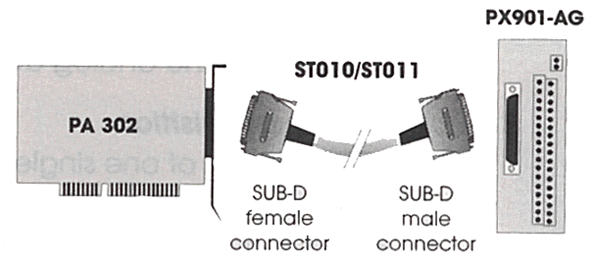
PX901-AG

Screw Terminal Board for DIN-rail

ST010/ST011

Standard Shielded, Twisted pairs Round ÄÉÀ̺í, 2m/5m


PA302 Çϵå¿þ¾î »ç¾ç

Parameter

Descriptions

Analog Input

Number of Channels

16SE/8DIFF or 8SE/4DIFF

Resolution

12-bit

Max. Data Transfer Rate

(Single-ended without INA) 125 kHz

Conversion Time

3 §Á

Data Transfer


Data to the PC

- Through I/O Commands

- Interrupt at end of conversion(EOC)

Input Range

0-10V, ±10V, ±5V Jumper Selectable, 0(4)-20mA Optional

Input Impedance

1011 §Ù

Gain INA

(Instrumentation Amplifier)

10, 100, 200, 300, 500, 600, 700, 800 through Jumper,

intermediate values can be optained through resistor

Overvoltage Protection 

±12V

Trigger

Through Software, External Trigger or Programmable Timer

Interrupts(Jumper-Selectable)

IRQ 3, 5 for XT, IRQ 10, 11, 12, 14, 15 for AT

Timer

TImer Configuration

Timer 0

Timer 1

Timer 2

Acquisition Possibility

Timer 0

Timer 1 and 2


3 x 16-bit Timer(82C54)


892.857kHz through Jumper

Freely Programmable through Jumper

27.97kHz through Jumper


Time remaining until the Conversion of Single Channel Starts

Cyclic Timer-Couner, with automatic reload function of the

programmable counter value after time out. For generating

a defined time interval(with Interrupt possibility)

Digital

Number of Outputs

2 Digital Open Collector Output Channels

Max. Output Voltage

24V

Max. Output Current

50mA typ.

Protection Circuitry

Voltage Reversal Protection

Noise Immunity

Test Level


- ESD: 4kV

- Field: 10V/m

- Burst: 4kV

- Conducted radio interferences: 10V

Physical & Environmental Conditions

Dimensions

156 x 99 mm

System Bus

ISA

Space Required

1 slot XT(8-bit) or AT(16-bit)

Operating Voltage

+5V, ±5% from the PC

Current Consumption

200 mA typ.

Front Connector

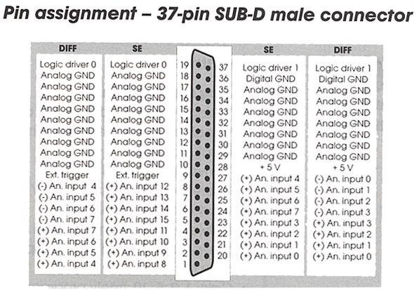
37-pin SUB-D male connector

Temperature Range

0 to 60 ¡É(with forced cooling)


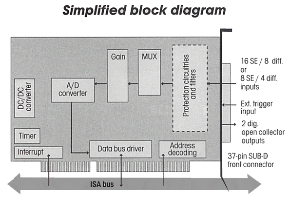
PA302 Block Diagram


PA302 Connector


PA302 Å͹̳Πº¸µå ¿¬°áµµ


Çѱ¹ÀÎÅÚ¸®Á¯Æ®½Ã½ºÅÛ(Korea Intelligent System)  ÀüÈ­ : 02-3272-9301   Email : sales@intelligent.co.kr