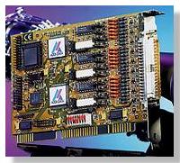
하드웨어 특징
![]() Acquisition of Incremental
Encoders
Acquisition of Incremental
Encoders
![]() Frequency Measurement
Frequency Measurement
![]() Pulse Width Measurement
Pulse Width Measurement
![]() Connection of 3 or
6 Incremental Encoder
Connection of 3 or
6 Incremental Encoder
![]() Possible Configuraion
Possible Configuraion
- 3 Channels, 32-bit Counting Depth,
Diff. or TTL on the Front Connector
or
- 6 Channels, 16-bit Counting Depth,
Diff. or TTL divided in 3 channels on the
Front connector and 3 on the connector
for ribbon cable
![]() Automatic Recognition
of Direction
Automatic Recognition
of Direction
![]() Mode with Single,
Double or Quadruple
Mode with Single,
Double or Quadruple
resolution
![]() Frequency Measurement
10MHz in Direct
Frequency Measurement
10MHz in Direct
Mode, 2.5MHz in Quadruple Mode
![]() 3 "Reference" Inputs reference Logic
3 "Reference" Inputs reference Logic
![]() 3 "Error" Inputs for error signals, External
3 "Error" Inputs for error signals, External
Strobe Inputs
![]() Software or Hardware Reset
Software or Hardware Reset
![]() 3 x 16-bit Timer(82C54)
3 x 16-bit Timer(82C54)
- Generation of Interrupts
- Strobe of the counters with
Timer-Defined Intervals
- Programmable Reference Frequency for
Frequency and Pulse Width Measure
![]() Interrupt with Timer or through External
Interrupt with Timer or through External
Strobe of the Counters
![]() 3 x 8 TTL I/O
3 x 8 TTL I/O
![]() Addressing through DIP switches to any
Addressing through DIP switches to any
address in the I/O space
![]() AT board with 16-bit access
AT board with 16-bit access
Safery Features
![]() All
Inputs protected against overvoltage
All
Inputs protected against overvoltage
through Transil Diodes
![]() All
Inputs with EMI or RC Filter
All
Inputs with EMI or RC Filter
![]() Detection
of line Interruption in
Detection
of line Interruption in
Differential Mode
![]() Standard
Drivers :
Standard
Drivers :
- Windows 2000/NT/98/95
- Windows 3.11, MD-DOS
![]() Real
Time Drivers :
Real
Time Drivers :
- Windows 2000/NT/98/95
![]() LabVIEW
5.01
LabVIEW
5.01
![]() Samples
programs :
Samples
programs :
- Microsoft VC++ 5.0
- Borland C++ 5.01
- Visual Basic 4.0/5.0
- Delphi 1.0/4.0
![]() On
request :
On
request :
- LabWindows/CVI 5.01
CE Certification
![]() EN
50082-2, EN 55011, EN 55022
EN
50082-2, EN 55011, EN 55022
응용 분야
![]() Event
Counting
Event
Counting
![]() Industrial
Automation
Industrial
Automation
![]() Frequency
Measurement
Frequency
Measurement
![]() Period
Measurement
Period
Measurement
![]() Pulse
Width Measurement
Pulse
Width Measurement
![]() Pulse
Generation
Pulse
Generation
![]() ...
...